index
- Press-Fit Connectors
- Solderless Connection with the Press-Fitting Technology
- Insertion Force and Retention Force
- Application of Press-Fitting Technology
- Forms of Press-Fit Terminals
- Packing of Press-Fit Terminals
- Sleeve(Pin holder)
- Materials of Press-Fit Terminals
- Surface Treatment of Press-Fit Terminals
- Specifications of Circuit Board Through-Holes
- Q&A
- Appearances and Shapes of Press-Fit Terminals
- Press-Fitting Machines and Jigs
- FINECS’ Solutions
- Connector terminal of FINECS that contributes to the electrical contact
Press-Fit Connectors
Recent years have seen an increased use of solderless press-fit connectors in the assembly processes of devices with circuit boards. In contrast to conventional connectors that are soldered when they are attached to the board, press-fit connectors can be attached by simply press-fitting them, simplifying the production process. More specifically, it is possible to eliminate the solder application and reflow processes. The simplified solderless mounting process leads to the reduction of energy consumption, establishment of an eco-friendly production process, and significant reduction of production costs.
In addition, with the increasing social call to reduce harmful substances and environmentally damaging substances, all manufacturers, regardless of their specialties, are required to produce products that do not contain such substances.
Press-fit connectors provide solutions for production processes that meet the needs of the times.
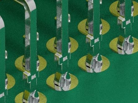
The terminals (press-fit parts) of a press-fit connector are inserted into through-holes in the printed circuit board, where pressure is applied due to the deformation of the press-fit sections, causing contact between the holes and the terminals to pass electric current. In other words, the press-fit section of each terminal forms a tight fit with a through-hole in the printed circuit board due to the restoring force generated as a result of the elastic deformation at the time of press-fitting. This tight-fit state maintains the contact to allow electricity to pass through.
In order to achieve this state, the press-fitting machine is required to have enough power to insert the terminals. In most cases, when mounting a press-fit connector on a circuit board, the connector is lightly fitted into the board by hand before it is fully inserted and mounted using a connector press-fitting machine. A special press-fitting jig is also required to mount a press-fit connector onto a printed circuit board.
Solderless Connection with the Press-Fitting Technology
The solderless connection is a method of mounting a connector onto a circuit board. This mounting method involves press-fitting an elastic contact (which deforms when force is applied, and becomes restored when the force is released) called the compliant section or press-fit section into a through-hole in the printed circuit board to create an airtight (gastight) contact with the inside surface of the through-hole utilizing the deformation of the elastic section of the contact.
This technology, developed in the US, is not a novel one but a mature technology, which has been mainly used for the mounting of multipolar connectors on motherboards. Individual connector manufacturers created their own specific shapes for the compliant section to give elasticity to terminals and obtained patents. The terminals were provided with cut sections at which they would elastically deform.
Their advantage is that terminal pins, or the entire connector, can be replaced in the event of a problem such as the bending of a terminal after mounting (it is possible to insert a new terminal into the same through-hole up to three times or so under normal conditions).
It is essential to appropriately control the press-fitting force and to dimensionally control the drilled inside diameters and the plating thicknesses for the through-holes.
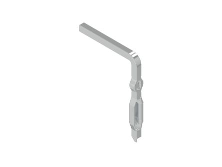
Shape of Press-fit pins/terminals
We recommend the Eye of needle type. Please contact us for other shapes.
* Requested to search for patent information related to the shape.
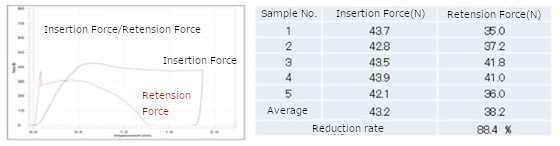
Insertion Force and Retention Force
The following shows an example of insertion force and retention force with a printed circuit board for evaluation.
Printed circuit board specifications
Board material: FR-4
Board thickness: 1.6 mm
Hole diameter: ø1.10 ± 0.05
Surface treatment: Gold flash plating on copper undercoat
Terminal specifications
Material: Phosphor bronze square pin (square of side 0.64 mm)
Surface treatment: Tin reflow plating on nickel undercoat
Application of Press-Fitting Technology
Environmentally damaging substances or the use of lead-free solder can lead to non-negligible deterioration in solder reliability. In addition, there have emerged various issues, such as the necessity to avoid thermal shock to the chip components due to soldering heat and the need for automatic mounting. Reflecting these circumstances, press-fitting technology is applied, for example, to connections between automotive control system circuit boards such as those for onboard equipment, antilock braking systems, vehicle stability control, navigation systems, hybrid drive systems, and tire pressure monitoring systems.
Press-fitting technology, which enables easy removal of connectors and other such components, is also advantageous when it comes to compliance with the Waste Electrical and Electronic Equipment Directive (WEEE Directive) in Europe. Accordingly, the application of this technology has also been expanded to conventional consumer products, including personal computers, servers, and multifunction printers.
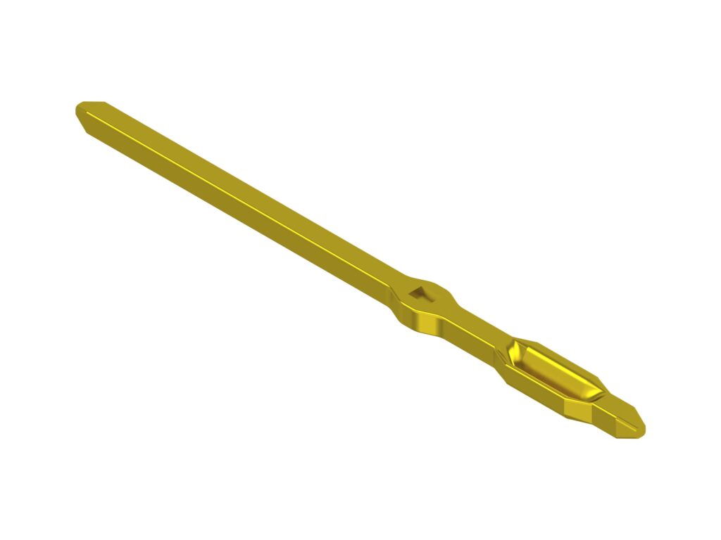
Forms of Press-Fit Terminals
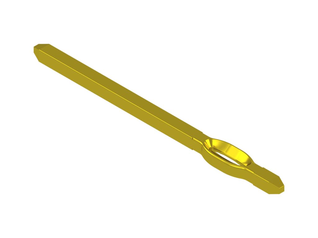
EON(Eye of needle)shape.
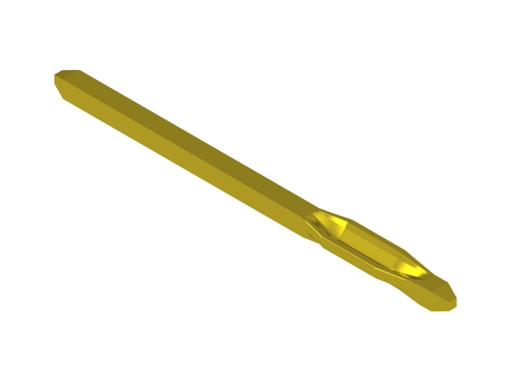
The cross-sectional shape is U-shaped.
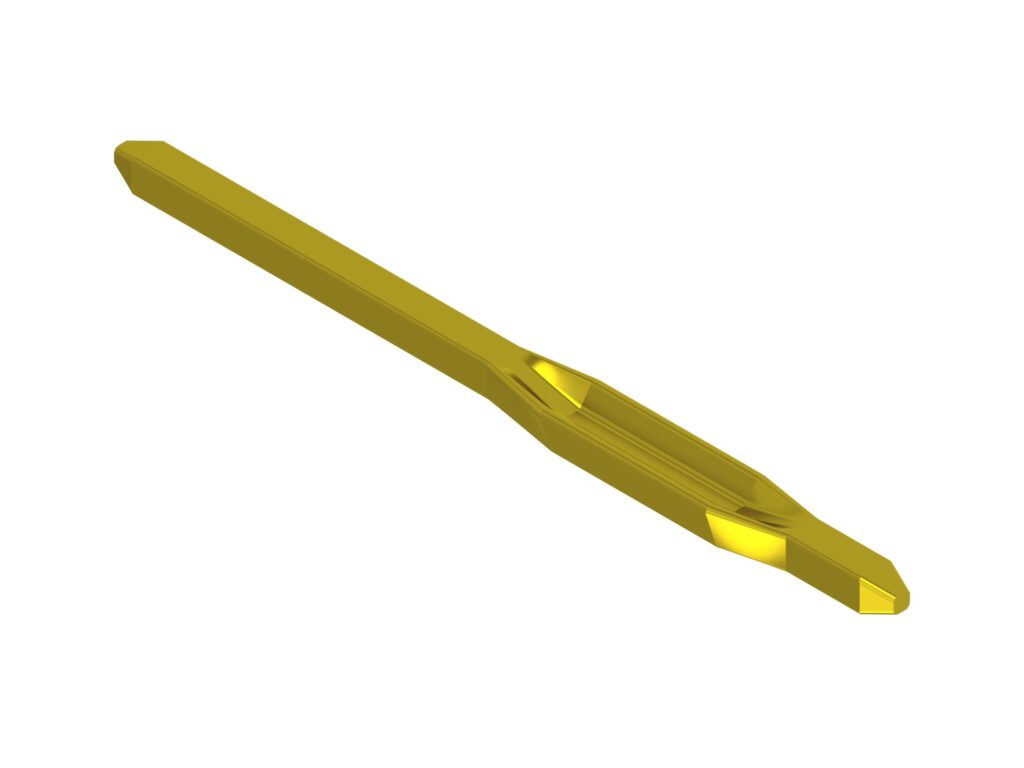
The cross-sectional shape is H-shaped.
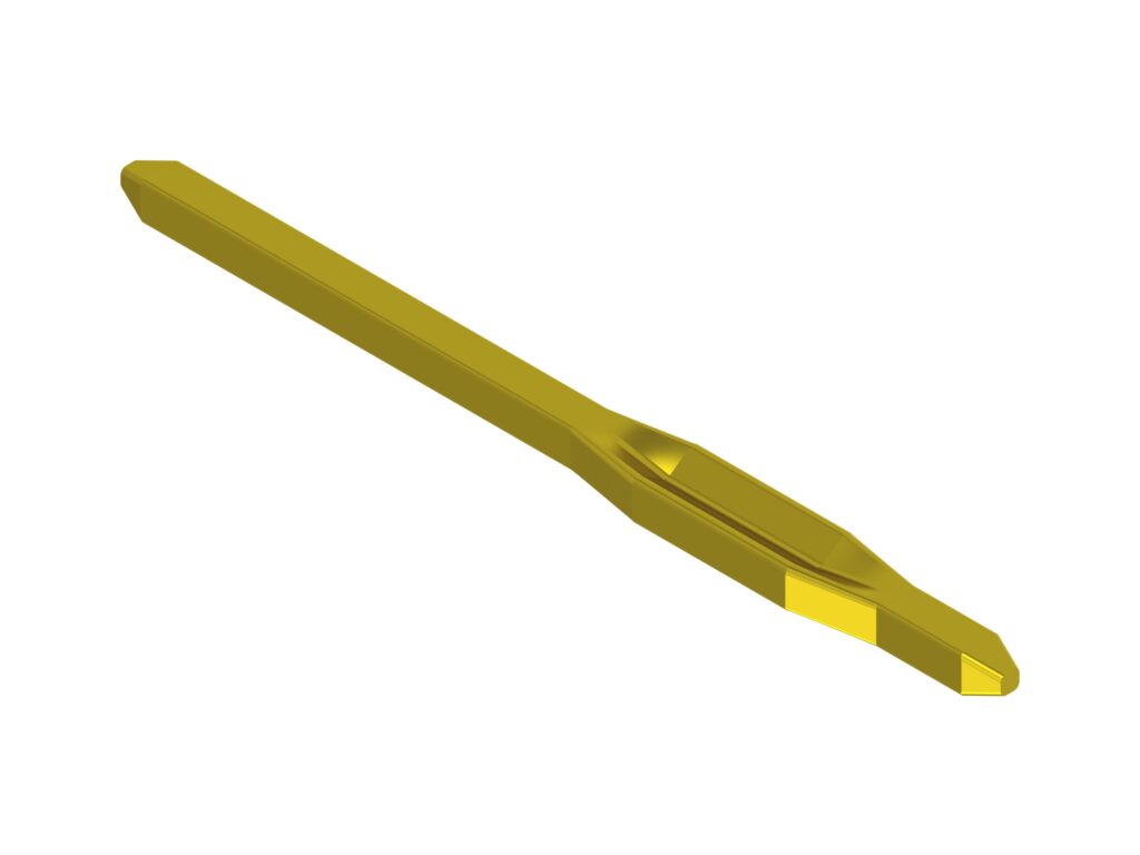
The cross-sectional shape is M-shaped.
Please contact us for other shapes.
* Requested to search for patent information related to the shape.
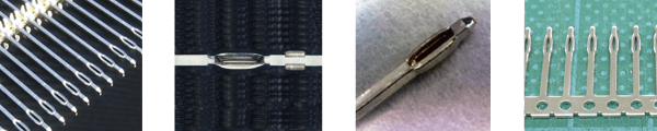
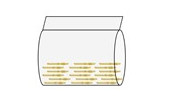
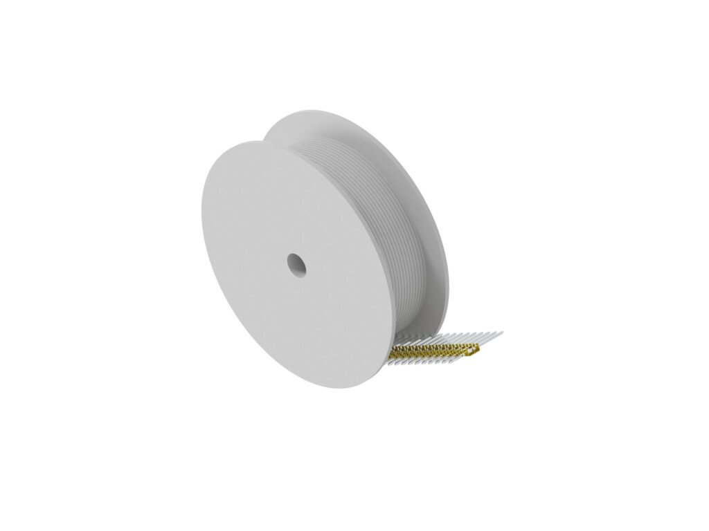
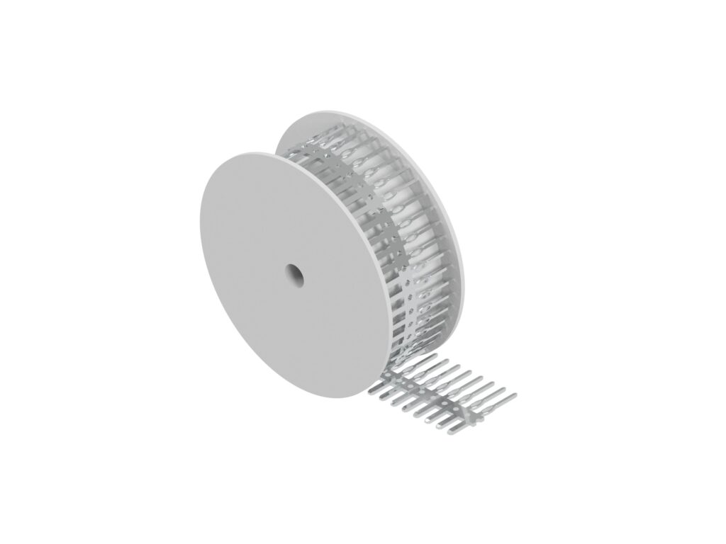
Packing of Press-Fit Terminals
FINECS produced Press-fit terminals from wire material and hoop material.
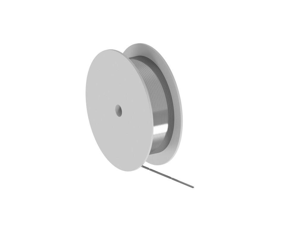
1) Press-fit terminal which is produced from a wire.
Various production is possible by our original cold heading technology.
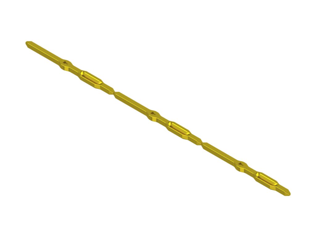
It will be delivered by winding it on a reel with the terminals connected.
It contributes to the rationalization of the assembly process.
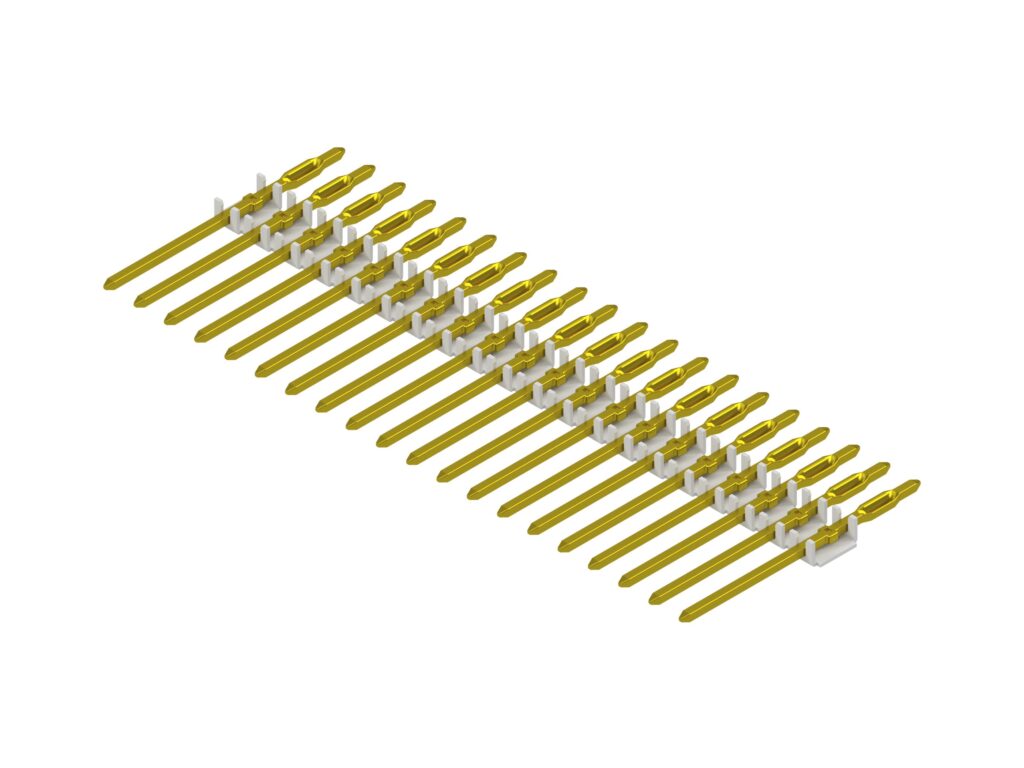
2) Press-fit terminal which is produced from a hoop material.
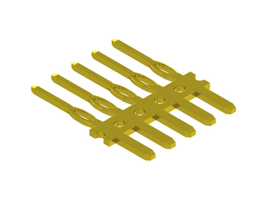
It is suitable for insert products because both ends of the terminal are plated.
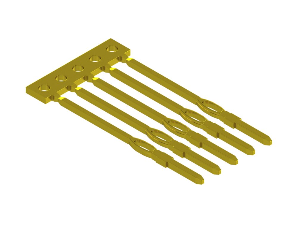
The carrier is on one side, it can be assembled in the same process as a general connector such as gang press fitting.
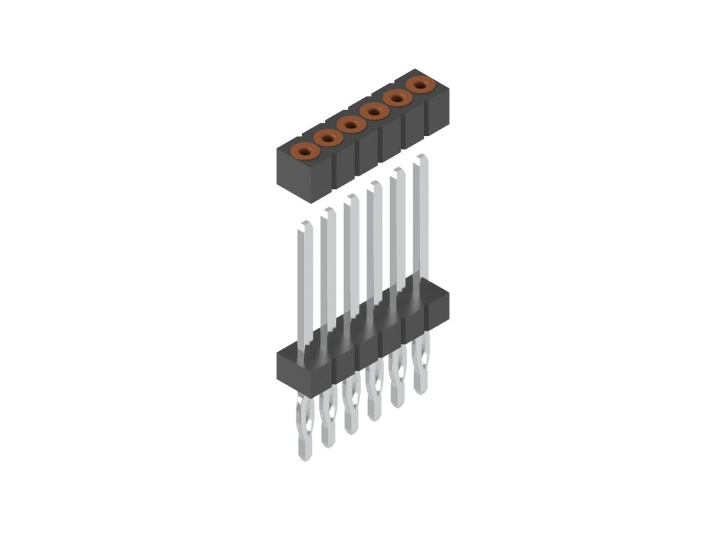
Sleeve(Pin holder)
Solid-shape Press-fit connection using the Sleeve(Pin holder).
Press-fit portion of the terminal side, is the corner post of the rectangle. It is used in press-fitted to the inner diameter of the other party of the sleeve.
The Sleeve, leave soldered to the substrate. It can be used in the ceramic substrate or other.
The Sleeve functions similarly to the through-hole of the printed circuit board.
Type of Needle
Materials of Press-Fit Terminals
1) Applicable Printed Circuit Board Materials(designations and corresponding JIS standards)
Recommendations:
FR-4.0 and FR-4.1: JIS C 6484:2005 (Base materials for printed circuits — Epoxide woven E-glass laminated sheet of defined flammability (vertical burning test))
<Explanation as to Printed Circuit Boards>
flame retardant grade
flame retardant grade
The FR (flame retardant) grade is an indicator of incombustibility of a copper-clad laminate, a structural component of a printed wiring board.
It is represented as “FR-X,” where X is a numeral between 1 and 6, and the most nonflammable grade is FR-6.
The printed wiring boards that are familiar to electronic equipment designers are FR-4 boards. This means that they are printed wiring boards that include copper-clad laminates graded as FR-4. FR-4 boards are copper-clad laminates with an ordinary level of heat resistance made using flame-retardant glass-cloth epoxy resin.
Copper-clad laminates graded as FR-5 may be used for printed wiring boards that require a higher level of heat resistance, such as those for automotive applications. Incidentally, new designations have been adopted in the revised UL standard, as follows:
- FR-4 products (Brominated flame-retardant products) changed to FR-4.0
- FR-4 products (Non-halogen flame-retardant products) changed to FR-4.1
2) Materials for Press-Fit Terminals (designations and corresponding JIS standards)
Recommendations:
- Phosphor bronze
- C5191W: JIS H 3270:2012 (Copper beryllium alloy, phosphor bronze and nickel silver rods, bars and wires)
C5212W: JIS H 3270:2012 (Copper beryllium alloy, phosphor bronze and nickel silver rods, bars and wires)
- C5191W: JIS H 3270:2012 (Copper beryllium alloy, phosphor bronze and nickel silver rods, bars and wires)
- Copper-beryllium alloy
- C1720W: JIS H 3270:2012 (Copper beryllium alloy, phosphor bronze and nickel silver rods, bars and wires)
- Corson copper alloy ; Cu-Ni-Si based (Corson alloy)
<Explanation as to Materials>
The material used needs to be elastic inside the through-hole in a printed circuit board. In other words, material with a high level of spring-like property is to be used. Material prices should also be considered.
When using beryllium alloy, it is necessary to consider the precipitation hardening treatment.
FINECS processes both metal strips and wire.
Please feel free to contact us.
Surface Treatment of Press-Fit Terminals
1) Tin reflow plating on nickel undercoat on wire
Ni: 1–1.5 µm + Sn: 1.5–2.5 µm (reflow plating)
2) Bandolier pins: It is also possible to apply gold plating to only the end portions of terminals.
Arrangement pitch: 2.0 mm, 2.54 mm (0.1"), 3.0 mm, etc.
<Recommended Through-Hole Specifications>
In addition to hot air leveling (HAL), the specifications listed below have become increasingly important. Based on different characteristics, such as mechanical strength and the coefficient of friction, we recommend the following through-hole specifications.
1.6mm以上 Thickness of the printed circuit board: 1.6 mm above
Specifications of Circuit Board Through-Holes
Prepared hole diameter: 1.20 ± 0.05 mm
Copper: 25 µm at the minimum
max.0.8µm Tin: 0.8 µm at the
Finishing diameter: 1.05–1.15 mm
Referential Standard
We have acquired reference data in connection with the standard mentioned below. For other tests, we ask that your company acquires the relevant data.
- IEC 60352-5:2012
- Solderless connections
Part 5: Press-in connections –General requirement,test methods and
- Solderless connections
-Excerpt-
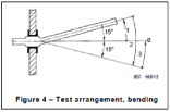
5.2. Mechanical tests
5.2.2.1 Bending
Bending of 15 degrees (one up-and-down movement in both directions)
5.2.3.4 Contact resistance
The contact resistance shall be carried out in accordance with IEC 60512,test 2a.
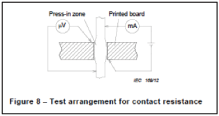
Requirements after mechanical, electrical or climatic conditioning:
a) Qualification test schedule: The maximum change of contact resistance
shall be less than 0.5mΩ for each test phase.
b) Application test schedule: The maximum change of contact resistance shall be specified in the component detail standard, if any, or in the manufacturer’s specification.
5.2.4.4 Dry heat
The test shall be carried out in accordance with IEC 60512, test 11i.
- test temperature 105℃
- test duration 1,000 h
Q&A
Q : How much can you handle the order quantity? (Including prototype)?
A : We support monthly production of 10,000 to hundreds of millions.
Q : Is there any burr or sagging?
A :Both the header terminal and the press terminal have a proven track record and reliability in processing that suppresses the occurrence of burrs and sagging.
Q : What are the features and price advantages of the wire press terminal and the strip press terminal?
A : We can manufacture press-fit terminals made by stamping wire rods and press-fit terminals made by pressing hoops.
Press-processed press-fit terminals have a high degree of freedom in shape, so they can be used in a wide range of shapes, but on the other hand, the initial cost tends to be higher than that of processed wire rods.
On the other hand, press-fit terminals for wire rod processing have no material loss and can be manufactured at low initial cost, but it is difficult to handle complicated shapes.
We will propose the most suitable processing method for the terminal under consideration, so please feel free to contact us.
Q : Do you evaluate the press-fit?
A : We have a many environmental test equipment. Physical tests can also be obtained using public sector equipment.
Q : Can you cooperate with us regarding evaluation tests, etc.?
A : Of course it can be evaluated. Please contact us.
Q : Can you guarantee patents?
A : We cannot guarantee patents because we are a contract manufacturer based on specifications provided by our customers. Please check the related patents by yourself before adopting our products.
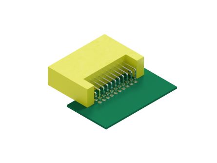
Appearances and Shapes of Press-Fit Terminals
1) Pin header(using Press-fit terminals)
(2~40Pin);2.54Pitch
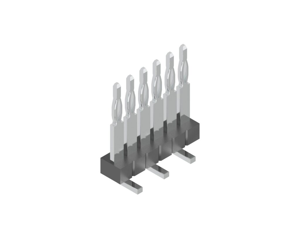
(2~40Pin);2.54Pitch
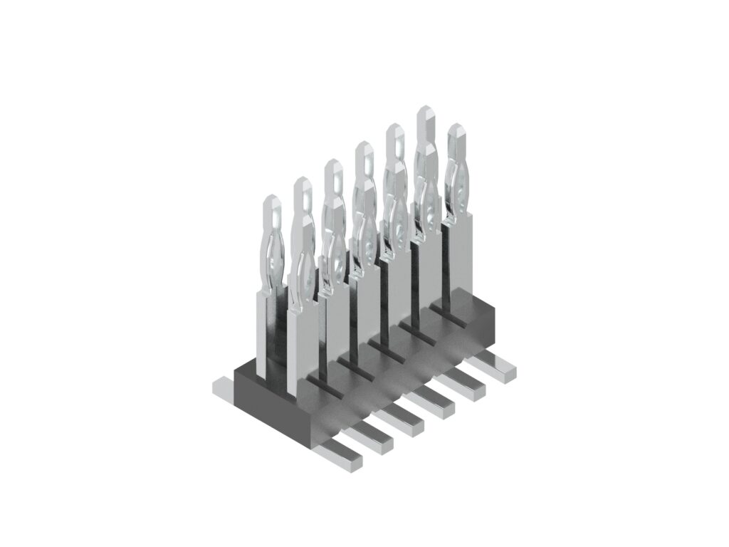
(4~80Pin);2.54Pitch
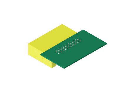
2) High capacity pin header(using Press-fit terminals)
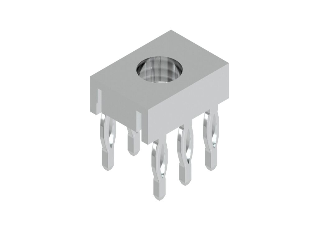
2.54Pitch*5.08
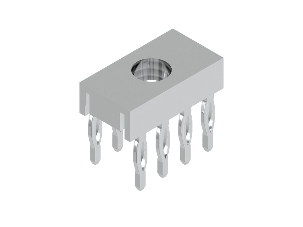
2.54Pitch*5.08
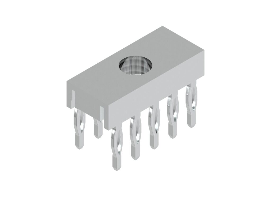
2.54Pitch*5.08
Press-Fitting Machines and Jigs
With early press-fitting machines for press-fit connectors, the connectors, which had been lightly fitted into the board, were positioned manually one by one and then fully inserted. In general, two types of press-fitting jigs are used: the upper jig and the lower jig. Each upper jig is shaped to be suited to the shape and direction of the press-fit connector to be inserted. The lower jig is made so that the circuit board will not be deformed by the pressure to insert the press-fit connector, and that any terminals of the press-fit connector will not be damaged when the terminals penetrate the through-holes of the circuit board and stick out of the lower surface of the board.
As a matter of fact, there are various shapes of press-fit connectors, and different press-fitting methods require different jigs for which setup changes are required. Therefore, it is necessary to standardize the methods for attaching and fastening jigs to the press-fitting machine.
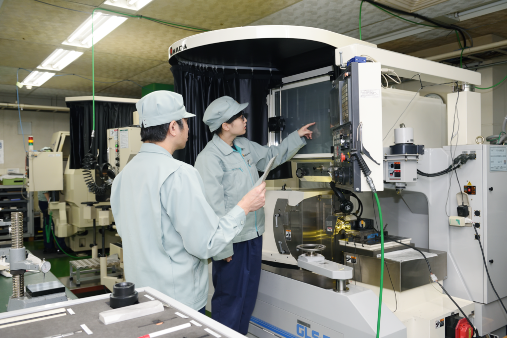
FINECS’ Solutions
We at FINECS have been involved over many years in the production of heading parts, such as PGA terminal pins, connector terminals, diode terminals, and rivets; the production of various kinds of heading machines and automatic precision electronic components assembly machines; and the automated assembly of precision electronic components. Based on the accumulated experience and knowhow, we provide solutions for press-fit terminals and press-fitting machines.
At FINECS, we work on producing press-fit terminal pins using both metal strips and wire.
For details, please feel free to call your nearest FINECS sales office or contact us via the form on this website.
Connector terminal of FINECS that contributes to the electrical contact
FINECS connector terminal is a key component that brings electrical contacts to a wide range of products. It is used in a variety of home appliances, digital devices, smartphones and mobile devices, PCs, automobiles, industrial machinery, robots, medical devices, aviation components, and automobiles.If the electrical contacts on a single connector lead to a conduction failure, the entire device will be defective, and a stable quality will always be required.
For more than 30 years, FINECS has produced connector terminals and pins processed from wire rods using in-house manufactured automated pin processing machines to meet the needs of a wide variety of customers.We are aiming to realize the world's highest QCD through low-cost, stable mass production, by automating the entire production process, from the wire plating process to the terminal processing machine, in-house designed and integrated in-house.Furthermore, through Value Engineering (VE), we strive to create the world's most valuable products that satisfy our customers' functions as connector terminals.We will continue to contribute to our customers and society through our proprietary "fine" proposals for a wide variety of connector terminals and pins.